External Trigger to Internal Pulse Generator: User supplied LVTTL signal triggers (on the rising edge) the internal generator to deliver the pulse. The pulse parameters are set in the internal pulse generator and the pulse is delivered from the internal generator.
External Trigger Pulse Generator: Pulse duration is the same as the external trigger pulse duration
LASER DIODE PIN CONFIGURATION
Type-1 Pin Configuration
Pulsed Laser Diode Driver, 1.5 Amps, 1 Nanosecond to CW, Integrated Butterfly Mount (TYPE 1)
Integrated Pre-Configured Butterfly Mounting Socket & TEC Temperature Controller
Models Available for All Butterfly Pin Configurations (refer to spec table below)
Built-In Pulse Generator and/or Remote Triggering
USB Interface, Includes Programming Tools Software Suite, DLL Library and GUI
Shipping Information
Shipping within the USA: $155.00
International Shipments: Shipping Account Required
Offered by: AeroDIODE Corporation, a Laser Lab Source Marketplace Seller
Orders fulfilled by: Laser Lab Source in North America
Sold & Supported in North America by Laser Lab Source
Orders for this product are processed and fulfilled by Laser Lab Source, the marketplace for Laser Scientists and Engineers. This item ships from Bozeman, MT USA. It is manufactured by Aerodiode, a Laser Lab Source Marketplace Seller. Mfg Part Number: CCS-STD
Warranty Information
This product is sold with a full one year warranty. It is warrantied to be free from defects in material and/or workmanship for a period of one year from the date of shipment. The warranty is transacted and honored by Laser Lab Source for product purchases made through Laser Lab Source.
Designed for precision pulsed laser diode applications, these PULSED laser diode drivers offer both pulsed and CW modes of operation. The CCS-STD units are designed to deliver clean pulses at pulse width’s as narrow as 1 nanosecond. These control and mounting modules deliver precision pulses which are generated internally by an on-board pulse generator, or on demand from your external TTL signal generator. These pulse drivers offer integrated laser diode protection to ensure that your laser is protected at all times. They include an efficient TEC controller which keeps the device under test delivering a highly stable output and protects it from thermal damage. A USB interface and graphical user interface offers the user complete control of the pulsing parameters. The user has control of amplitude, pulse width, rep. rate, temperature set point, current / temperature limits and more.
Flexible Laser Diode Pulse Generation and Output Synchronization:
These pulsed laser diode drivers offer the user the flexibility to choose from three different pulse generation sources. First, they include an internal pulse generator. Second, the user can choose to use an external trigger source. Finally, an external trigger source can be used to activate the internal pulse generator. If the user chooses to provide an external trigger source, the input pulse trigger is a TTL/LVTTL input voltage through an SMA connector. The input voltage range for the external trigger is 0 ~ 3.3 Volts. These units also provide the user with a sync-out port which allows synchronization of the driver to related test equipment. This SMA output port delivers an LVTTL copy of the CC-S logical driving signal.
Clean High Speed Pulse Performance ~ Laser Output Fiber Coupled to a Fast Photodetector and Oscilloscope:
Pin Configurations:
The CCS-STD can be ordered for any butterfly package pin configuration. Because impedance matching is a critical factor in delivering clean high speed pulse performance, the CCS unit is pre-set for your laser diode’s pin configuration. The standard default model is for a type 1 pin configuration. Please refer to the image carousel above to view available pin settings.
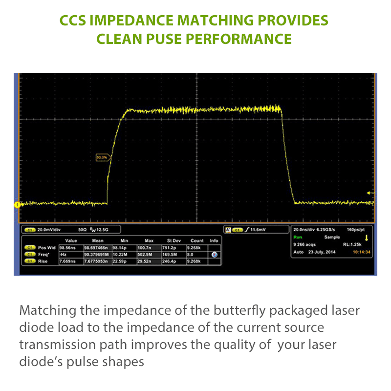
Pre-Set Impedance Matching Improves Your Laser Diode’s Pulse Performance:
When the impedance from the pulsed current source PCB is not properly matched to the butterfly package pins, significant pulse degradation can occur. This is often seen as distortion of the laser output pulses and/or overshoot of the pulses. The CCS pulsed laser diode driver is designed to reduce and/or eliminate this pulse degradation by matching the nominal impedance of the butterfly packaged laser diode with the pulse transmission line. Current sources inherently have a high output impedance and laser diodes have very low impedance. The most important requirement of proper impedance matching is matching the impedance of the load to the impedance of the transmission line. The inductance of laser diodes ranges from a few nanohenries to tens of nanohenries. From inductance theory, 𝑑𝑖/𝑑𝑡 is the rate of change in current over a specific period in amperes per second. The voltage increases with the inductance and with the rate of the change of the current. Energy stored in the inductor’s magnetic fields during the pulse has to be released when the pulse ends. This creates a voltage, which in turn creates a new current, which in turn creates a new magnetic field on the transmission path. This creates a “loop” which manifests as “ringing” on the pulse waveform and on other distortions to the pulse shape. The CCS current output transmission path has been carefully designed to match the current source impedance to the butterfly packaged laser diode.