Acousto Optic Modulator Basics and Set-Up Guide
Author: Stephen Gwinner
Publish Date: 07/06/24
QUICK SEARCH TABLE OF CONTENTS
- What is an Acousto Optic Modulator?
- How Does an AOM Work?
- How to Use an Acousto Optic Modulator and Set-Up Guide
- Shop Acousto Optic Modulators
- The Role of Bragg Diffraction and Diffraction Efficiency
- AOM Applications: Modulating the Light Emitted from a Laser Diode
- Key Advantages of Acousto Optic Modulators
- Factors to Consider when Choosing an AOM
What is an Acousto Optic Modulator?
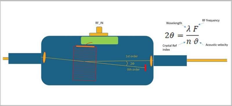
An acousto optic modulator, also known as a Bragg cell or an AOM, is an electro-optical device that uses sound waves to manipulate the properties of a laser beam. The basic principle of an acousto optic modulator is the interaction between laser light and sound waves within a specified medium. The laser beam is passed through the specified medium, for which commonly used materials are quartz, tellurium dioxide (TeO2), fused silica, indium phosphide and germanium. When the beam from a laser enters the medium, it encounters a sound grating. The sound grating is created by changing the refractive index of the medium by the oscillating mechanical strain of a sound wave. The sound grating diffracts the light. However, rather than a typical static separation caused by a Bragg grating, the AOM is designed to rapidly turn the laser beam on/off, or change its direction, intensity, and/or frequency. If you are new to the realm of modulating laser light, this series of videos provides a good overview and includes a section on acousto optic modulators:
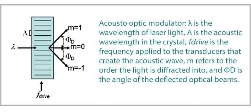
according to mλ= λ sin Λ sin θm

Caption: When the RF signal is OFF, the laser light is blocked. When the RF signal is ON, the laser light switches to the first order and is propagated into the fiber.
How Does an AOM Work?
For simplicity, this article will refer to the medium described above as a crystal. An electrical signal from an RF driver is applied to the crystal typically using a piezoelectric transducer. This transducer creates a sound wave. To be more specific, acoustic waves generated by the transducer propagate into the medium material causing pressure changes in the substance. The sound wave, which is typically on the order of a few watts of acoustic power, generates a traveling strain wave in the material comprising the medium. This is referred to as the photo-elastic effect. This leads to a traveling refractive index grating, at which light can experience Bragg diffraction. This is why AOMs are sometimes called Bragg cells. When a high frequency sound wave is introduced into the crystal, it creates a periodic variation in the refractive index, known as a sound grating or acoustic wave. The light that interacts with this sound grating can be diffracted, and the first-order diffracted beam will experience a frequency shift, which is the basis for modulation. This video provides a more in-depth technical description of how AOM’s work:
An RF driver is required for an acousto optic modulator to function. The RF driver output power is typically in the range of a few watts (1 Watt to 5 Watts) of electrical power. This RF driver signal is then applied to an input port, usually an SMA connector, on the AOM. Most companies who manufacture acousto optic modulators also manufacture compatible RF drivers. To get a more in-depth technical description of the design of and working principles of AOM’s, please refer to this article which explains new developments in AOM technologies as they apply to medical research: https://www.ncbi.nlm.nih.gov/pmc/articles/PMC9953934 .
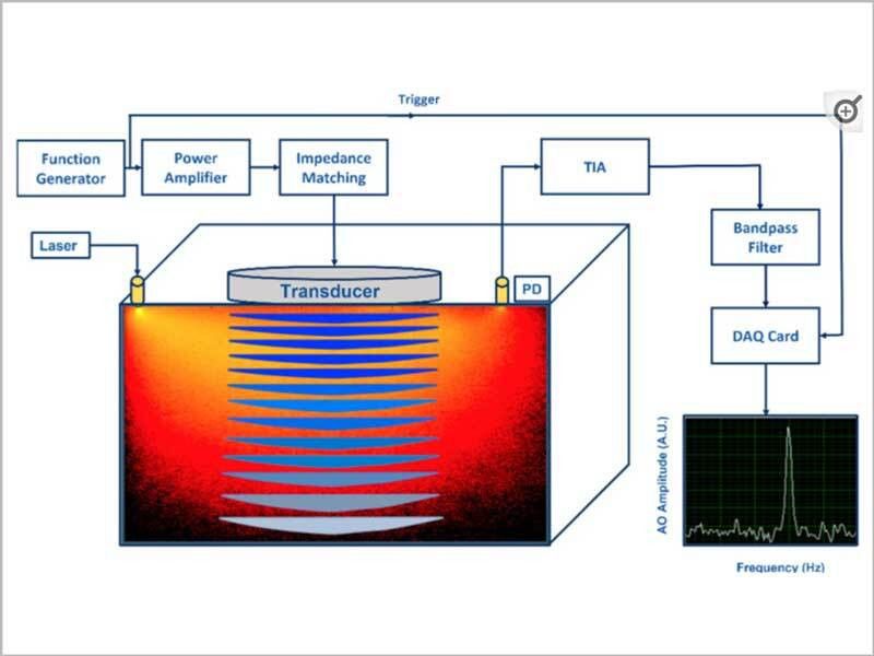
Caption: illustration of an AOM detection system
How to Use an Acousto Optic Modulator and Set-Up Guide
Always refer to the AOM and RF Driver product manuals for a step-by-step set-up guide. The steps below are just to provide a general overview of how the various components are connected and show an image of the test set-up.
To understand how to set-up and how to use an AOM, and how to set-up the RF driver and other components, I chose to compare the optical output signal of an AerDIODE fiber-coupled AOM to a Keithley function generator TTL signal on an oscilloscope. I wanted to compare TTL “before AOM and after AOM” plots on the oscilloscope.
Caption: How to Set-Up an Acousto Optic Modulator
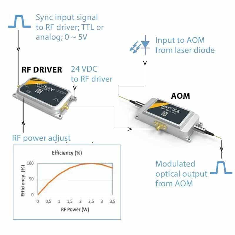
STEP 1: Check that you have the correct RF driver power level prior to connecting your RF driver to your AOM; never exceed RF power indicated on product data sheet; Fix bottom of AOM and RF driver to a heat conducting surface such as an optical table or heat sink with good thermal contact
Most AOM manufacturers offer their own RF driver. This makes set-up and integration very fast and simple. But you can also use your own RF driver. You will need to look at the RF power specifications ratings on the AOM data sheet to make sure you are providing the correct power level. In the example set-up below, after confirming that I needed 2W of RF driver power, I connected the RF driver to the AOM with the manufacturer supplied SMA cable. With the AeroDIODE AOM and RF driver, the impedance matched jumper cable is provided. Typically, you should always connect the RF driver to the AOM before powering up the RF driver or connecting power to the RF driver.
STEP 2: Connect TTL or Analog “Sync Signal” to the RF Driver
In the set-up example image below, I chose to use a Keithley function generator as a TTL “sync in” input to an AeroDIODE TTL signal RF driver. I used this approach because I could also use a separate output from the Keithley function generator to my oscilloscope as a reference. I set the Keithley function generator set to TTL, 10 kHz. Note that I did not turn on the AWG until I had connected the RF driver output to the AOM, connected 24VDC supply to the RF driver, and powered on the RF driver.
STEP 3: Connect RF Driver Output to AOM; Connect Power Supply to RF Driver
Do not leave the RF driver output port (connected to the AOM interface) unloaded / not connected to AOM. It is necessary to connect the AOM to the RF driver before powering on the 24VDC supply to the RF driver. I used a BK precision 24VDC supply to power the AeroDIODE RF driver. Because I was just doing a simple set-up test to understand how the components went together, I used alligator clips to quickly connect the DC power supply to the RF driver. But you can also solder the 24DC power supply leads to the DC input on RF driver. Keep the bottom of the AOM and RF driver fixed to a metal material like an optical table or a heat sink with good thermal contact.
STEP 4: Couple Laser Diode (CW mode) into Acousto Optic Modulator
For the laser diode input to the AOM, I used an AeroDIODE 1064nm butterfly packaged DFB laser running in CW mode. The laser diode was biased, temperature controlled and mounted in an AeroDIODE model CCS-CW driver and mount unit.
STEP 5: Connect Output of AOM to Photodiode and then to an Oscilloscope
I connected the optical output of the acousto optic modulator to an external fast photodiode. The photodiode was then connected to my oscilloscope.
STEP 6: Power on 24VDC supply to RF driver, power on AWG, power on Laser Diode
STEP 7: Compare TTL output from input of driver to TTL output directly from function generator
I compared the output of the AOM to the Keithley function generator output on the oscilloscope.
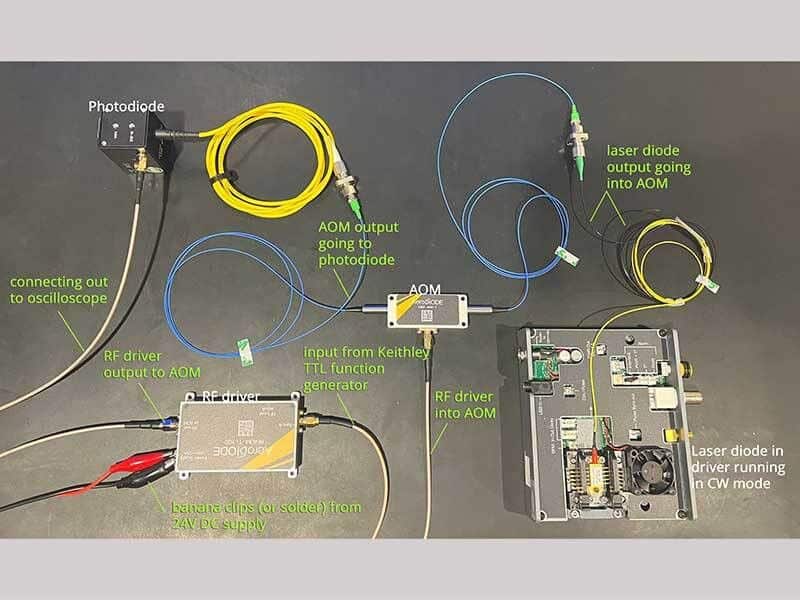
How to Use an Acousto Optic Modulator; Component Set-Up Guide (AeroDIODE products)
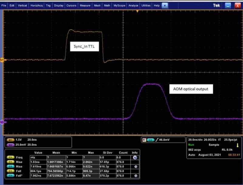
How to Use an Acousto Optic Modulator; Checking Results on an Oscilloscope
(Image courtesy of AeroDIODE)
Shop Acousto Optic Modulators
AOM’s are offered for wavelengths across the visible, near IR and IR ranges. They are typically optimized for a specific wavelength range of roughly 100 nm. AeroDIODE specializes in low insertion loss, high speed AOM’s:
- Shop 400nm acousto optic modulators AOM’s
- Shop 532nm acousto optic modulators AOM’s
- Shop 635nm acousto optic modulators AOM’s
- Shop 780nm acousto optic modulators AOM’s
- Shop 850nm acousto optic modulators AOM’s
- Shop 940nm acousto optic modulators AOM’s
- Shop 1064nm acousto optic modulators AOM’s
- Shop 1310nm acousto optic modulators AOM’s
- Shop 1550nm acousto optic modulators AOM’s
- Shop 1650nm acousto optic modulators AOM’s
The Role of Bragg Diffraction and Diffraction Efficiency
To understand acousto optic modulators, Bragg diffraction is the baseline concept. In this context, it refers to the interaction between the light wave and the sound wave in such a way that constructive interference occurs at specific angles. This is known as a Bragg angle. The Bragg angle is determined by the wavelength of both the incident light and the acoustic wave. Bragg’s Law helps in calculating the specific angle at which light will be diffracted optimally by the sound grating. The diffraction efficiency is simply the ratio of the diffracted laser intensity (power) to incident power.
AOM Applications: Controlling the Light Emitted from a Laser Diode
AOM’s are used to control the intensity and the duration of laser pulses. They are often used with fiber-coupled and free space semiconductor diode lasers. AOM based intensity modulation and frequency modulation of a laser diode’s emitted light is used in many applications. These applications include quantum computing, cavity dumping, mode locking, confocal microscopy, hyperspectral imaging, Q-switching of DPSS lasers and ultra-fast laser pulse-picking applications. For more information on AOM applications, this article is a helpful resource: https://www.spiedigitallibrary.org/conference-proceedings-of-spie/0222/1/acousto-optic–electro-optic-modulator-applications/10.1117/12.958642.short .
Key Advantages of Acousto Optic Modulators
- High Rates of Modulation Speed: AOMs can modulate light at a high frequency, commonly in the range 50 MHz to 200 MHz. This is fast enough to create active mode locking in an ultrafast laser, which is a key parameter for many applications including pulse picking.
- Non-Mechanical Architecture: Since AOMs use sound waves to modulate the light emitted from the laser, there are no moving mechanical parts involved. This results in relatively high reliability and long lifetimes.
- Versatility: With the ability to precisely control several different beam parameters, acousto optic modulators are more versatile than other alternative modulator technologies.
Factors to Consider when Choosing an AOM
When selecting the best Acousto Optic Modulator for your project, there are several specifications and operational factors to consider:
- Frequency Range: The AOM should operate within the frequency range required for your application. AOM’s are commonly offered in the 10’s to 100’s of MHz range.
- Medium Material: The material of the AOM affects its performance, including the efficiency of light modulation and the achievable frequency range. Common materials used are crystalline quartz, tellurium dioxide (TeO2) and fused silica. The medium material is typically shown on the product data sheet.
- Diffraction Efficiency: The diffraction efficiency of the modulator determines how much of the input light is converted into the first-order diffracted beam. Higher efficiency is typically desired for most applications.
- Maximum Laser Power Rating: Consider the laser power that the AOM will need to manage. High-power applications require AOMs with high power ratings and good thermal management to avoid damage.
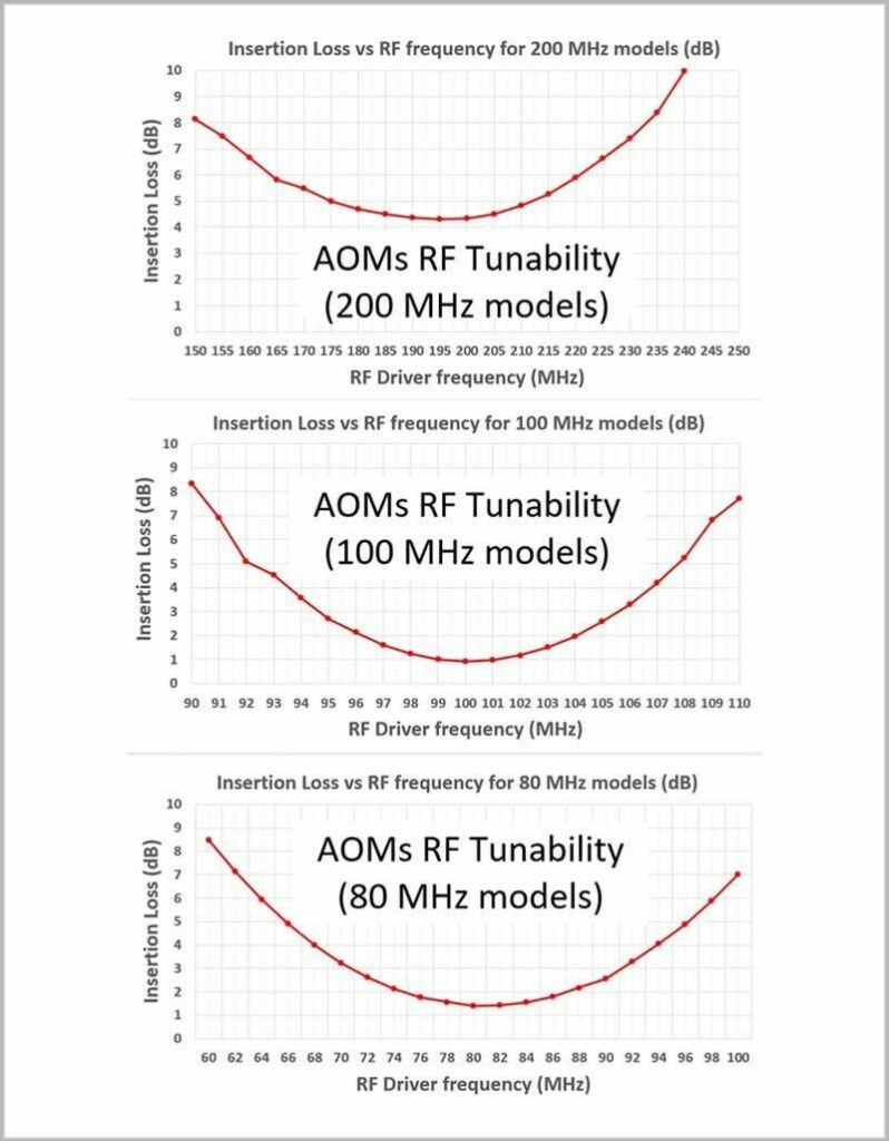
- Insertion Loss: With acousto optic modulators, there is often a choice to be made between the desired switching speed and the insertion loss. Increased switching speed typically results in higher insertion loss. The insertion loss for most AOM’s is typically around 3 to 5 dB. However, insertion loss values down in the 1.5 dB range are more desirable and are available. The more the optical beam is focused within the AOM’s embedded crystal, the faster it switches, but the more difficult it can be for the light to reach the output fiber without suffering losses.
- Rise / Fall Time (switching speed): High speed AOM’s with approximately 10 nanoseconds rise and fall time values are often preferrable. As mentioned above, faster switching speeds are usually penalized with higher insertion loss.
- Extinction Ratio: Extinction ratio values in the 40 to 50 dB range are typically preferrable for a fiber coupled AOM.
References:
“Crystal Optics: properties and applications”:AK Bain ,2019, books.google.com
“Optical Switching” D Nandi, S Nandi, A Sarkar, CK Sarkar, Wiley Online Library
“Design considerations for acousto-optic devices” JEH Young, SK Yao,Proceedings of the IEEE, 198, ieeexplore.ieee.org
“Basics of acousto-optic devices” Lekavich, J. (Apr 1986), Lasers and Applications