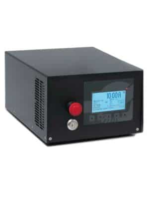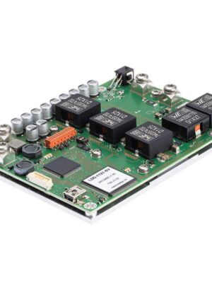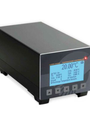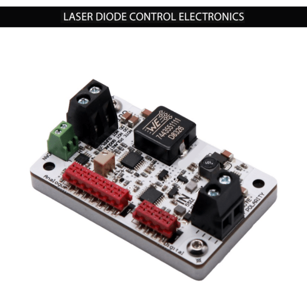
LASER DIODE CURRENT & VOLTAGE
- Output Current Range (I): 0 ~ 10 Аmps
- Output Voltage (V): 5 ~ 40 Volts
- Current Setpoint Step Size: 0.01 Amps
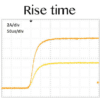
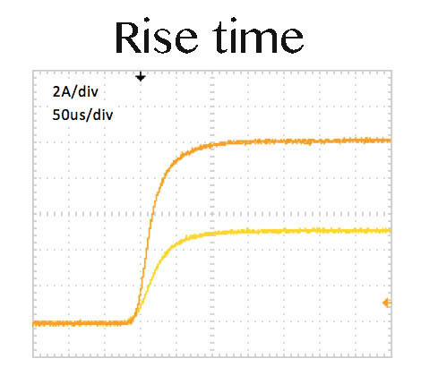
- Rise Time: (Iout = 5A) min - 60μs; max - 100μs
- Rise Time: (Iout = 10A) min - 60μs; max - 100μs
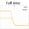
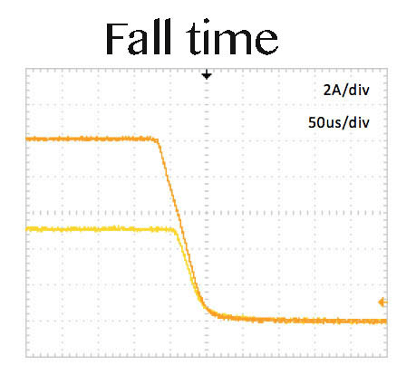
- Fall Time: min - 20μs; max - 80μs
- Current Stability: <0.2 %
- Current Setpoint Absolute Accuracy: <1 %
LASER DIODE PROTECTION
- Soft-Start Ramp to Current Setpoint
- User Adjustable Current Limit
- Over-Current Protection Fast Shutdown
- Over-Temperature Thermal Warning and Shutdown
- Reverse Current Protection
- Crowbar Circuit Protection
- Disable Input
- Interlock
DIMENSIONS AND WEIGHT
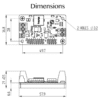
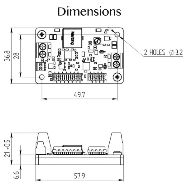
- Dimensions: 37 mm x 58 mm x 21 mm
- Weight: 50g
USER INTERFACE
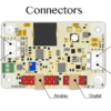
- Analog Control Signal Connector
- RS232/UART Digital Interface
- Enable / Disable Input Signal Input
- User Adjustable Trim Potentiometer Current Limit
- USB Optional: $35.00 (Option UART-USB)
INPUT
- Input Voltage Range (Vin): 12V to 55V
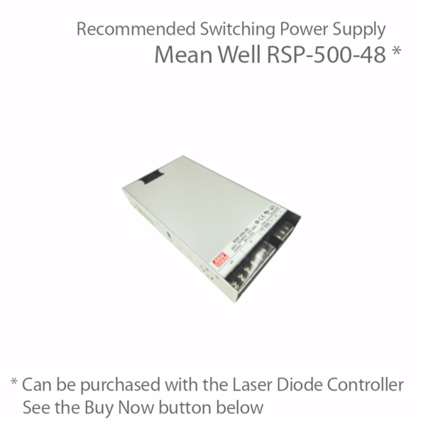
- Recommended Switching Power Supply: Mean Well RSP-500-48, available for purchase with this laser diode controller
SHIPPING KIT (INCLUDED PARTS)
- Laser Diode Driver
- 50 cm ribbon cable with one 8-pin connector – 1 pcs
- 50 cm ribbon cable with one 14-pin connector – 1 pcs
- Datasheet & User Manual – 1 pcs
- Current Output Cable Not Included
WARRANTY PERIOD
- 1-Year Manufacturer's Warranty
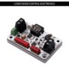
10 Amp Laser Diode Driver / 40 Volts Compliance Voltage Range
Key Features
- High Compliance Voltage Range for Multi-Emitters and Laser Diodes Connected in Series
- Soft-Start Current Ramp, Current Limit, Reverse Voltage Protection
- Analog Control Signal/ RS-232 / UART (USB Optional, $35)
- NTC Thermistor Input for Laser Over-Temperature Fast Shut-Down
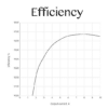
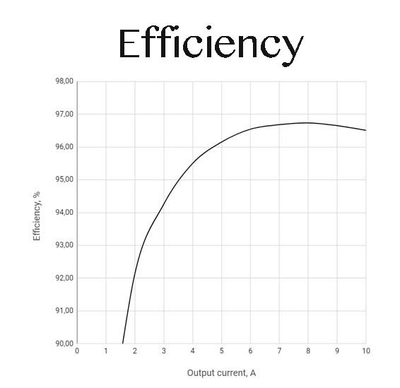
- Very High Efficiency up to 95%
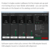
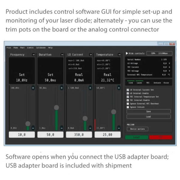
- Free Control Software with GUI ---------------------------5% Discount for Orders > 5 Units
Shipping Information
Shipping rates in the USA:
– All products: $25.00
– Please contact us for International Shipping Rates
Warranty Information
This product is sold with a full one year warranty. It is warrantied to be free from defects in material and/or workmanship for a period of one year from the date of shipment.
|
Weight |
1 lbs |
|---|---|
|
Dimensions |
10 × 8 × 6 in |
|
Current Range |
5 Amps - 25 Amps |
|
Voltage Range |
25 Volts - 150 Volts |
|
Form Factor |
Board (no enclosure) |
|
Computer IO and Software |
GUI software included, RS-232 or 485, USB Available |
|
Driver Current |
10 A |
|
Driver Voltage |
40 V |
|
Maiman Model Number |
SF6040 |
Product Overview
10 Amp, 40 Volt High Power Laser Diode Driver Module Overview
These precision driver modules offer up to 10 amps of bias current and up to 40 volts to your laser diode. These small footprint drivers were designed to power the latest generation of high power multi-single emitter pumps in the near infrared range. They are used in laser systems to bias lasers in series and pumps that are based on multiple single emitter designs. These model SF6040 drivers are designed for demanding system integration applications which require the highest levels of reliability. They also offer a very affordable choice for laboratory research applications. The SF6040 model has been updated with an integrated NTC thermistor monitor circuit to provide fast shut-down of the output current to the laser if a maximum temperature limit is reached. They also offer an improved 0.01 amp set-point resolution for precise control of the output current.
Review of SF6xxx Series Laser Diode Protection Features
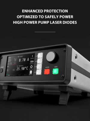
The SF6xxx Series drivers provide protection features which are simple to set-up and more than adequate to protect your LD. They include an over current protection circuit with a user adjustable limit, a soft-start current ramp, and an over-temperature shutdown. Additional features to protect your high power laser diode include reverse current protection and crowbar circuit protection. The crowbar circuit is a fast shorting clamp which is activated in over-current, open circuit and over-temperature events.
Sourcing Current to your Laser and the Crowbar Clamp Protection
The modules are initially enabled by applying an active high 3.3V ~ 5V DC compatible logic input signal. The driver sources current and begins to operate when the 5V input enable pin is high. To ensure that the current enable is applied without overshoot, a slow start sequence initiates when the enable pin is set high. The enable pin can also be used in the quasi-CW mode. The output current is set by applying an analog signal to the current set pin on the control connector. The current set pin can be used for analog modulation by applying sign wave, square wave or ramp signal. The output may be pulsed by applying a TTL square signal to enable pin. The minimum pulse duration 500 microseconds.
These high power drivers offer a highly reliable crowbar clamp to short the current and disable power to your laser diode. There is a pin on the control connector which shows the crowbar protection circuit status. The crowbar will short the output while the module is in an over-current shutdown or an over-temperature shutdown mode.
Multiple Control Interfaces
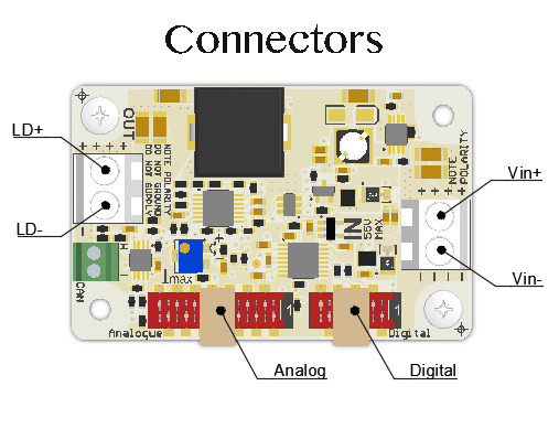
The model SF6040 offers the user multiple interface methods to set and measure the modules parameters. For simple, fast start-up, the module has trim potentiometers which the user can access on top of the control board. This manual mode of control is typically used to make sure the driver is functioning properly prior to connecting the laser. For complete control of all parameters, the user has the choice of using an analog control signal connector or a digital interface. The 8 pin RS232 / UART digital interface and the 14 pin analog control connector are both described in detail in the attached brochure.
Driver Safety Interlock, Current Monitoring and Voltage Monitoring
These SF6xxx units have an interlock pin which must be connected to the ground order for output current to be enabled. The safety interlock is used to shut-down the module with a logic high signal triggered by and external interlock trigger such as a door to the lab or an external over-temperature circuit. These modules also have an on-board temperature sensor which will shut-down the output when the temperature exceeds a pre-set temperature. The output voltage of the driver can be monitored by a linear scaled voltage monitor output, 0~1V. The voltage is measured between LD+ terminal and GND. The current can be monitored by a linear voltage output, 0~1V = 0~3A also with +/-2%.
Recommended Power Supply
The OEM laser module requires an external power supply, such as the Mean Well RSP-500-48. This power supply is available as an add-on to the order, and can be found in the Cart.
